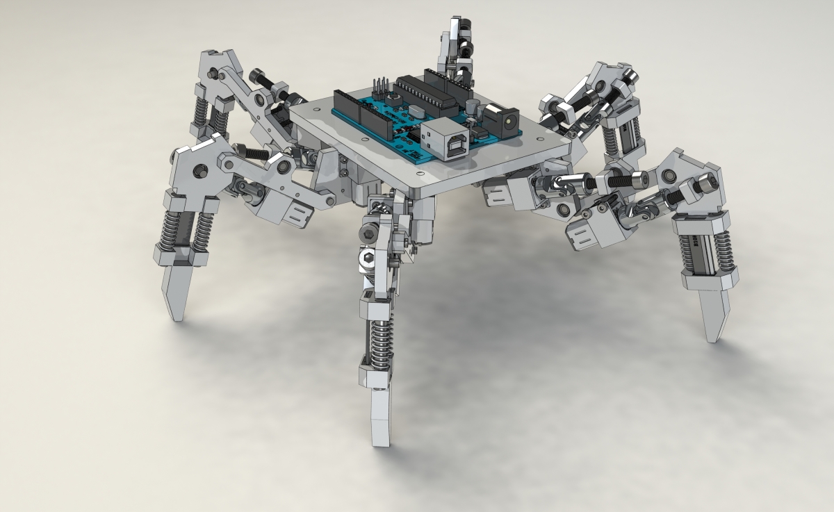
This is a robot I designed in summer holiday in 2012.This design is mainly a Solidworks modeling practice.I tried to use CAD software and simulation to verify my idea instead of trial and error with the gears,which was what I used to do.I did some analysis on the leg structure by hand at first,but it turned out to be very complicated.So later on I turned to use Solidworks to simulate the legs.The project was abandon later on because I had to put my effort in my CNC project,which lasted for more than two years.But I decided to post it out and maybe someone is interested in such a screw driven mechanism and my work could make some small contribution.
I posted an article a few years ago in a forum(Chinese).In that post I posted a bunch of calculation and analysis about the leg structure.I’ll try to move those content here from time to time because it’ll take some time to pick up what I thought a few years ago.
So the main problem I wanted to solve is how can I design the mechatronics system to control the leg.The problem involved the torque and speed of the motors,lead screw selection,and linear feedback potentiometer calculation.
I’ll just post some picture of the robot first.


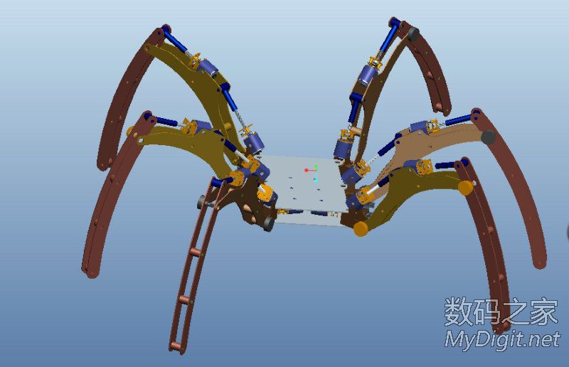
Here’s vesamount‘s design of a similar structure.He used 6v 700~1000rpm motors to drive the legs.And he tore down the servo and used the PCB and potentiaometer inside to drive the motor and do feedback control,which saved lots of work of building his own motor driver system.


to be continued..

Hi Malcolm,
I’m interested in your project as this was also my idea for my final year project. I’d like to know more about this project of yours as it may help me in mine too. Would you mine enlightening me?
Regards,
Edward
LikeLike
Dear, malcolm,
Although I am Chinese, but I can’t read Mandarin though. So I cant really understand your explanation in your forum.
Regards.
Edward
LikeLike
Hi Edward!
I’m kind of busy these days so I don’t have the time update his post,but here’s the gist of my old post:
1.screw driven mechanism,motor rotation motion to linear motion,which again turn into rotation motion by pushing or pulling the leg.
2.find the kinetics equation for such structure.
2.define the speed you want for this robot and calculate the speed and torque requirement for motors using the equation.
3.anyway the equation in my post could be wrong so I’ll suggest you to use solidwork to simulate the motion if you have access to solidworks.
After this then you might want to start the eletrical system design.You need three motor drivers(LG9110 would suffice),three tiny potentiometer(like those in servo) for feedback control.If you wanna go further you can add linear potentiometer to detect the force of each leg.
On the last page of the article someone posted a real hexapod which is similar to my design.Its legs are long and moves very slow and it seems like purely open loop control.That might gives you some ideal of how this robot works out.
LikeLike
Very Cool, Do you have some testing videos?
LikeLike
Sadly no,it’s just a concept
LikeLike
Very Cool! Do you have some testing videos for this?
LikeLike