This post records my favorite CNC machine I’ve ever built.It’s actually the third machine I built and it’s an improvement of the previous one.Since I’ve already had a machine before building this one so I have the ability to make more complicated parts which I wasn’t able to make before.My goal is to make a compact desktop CNC milling machine so that I can implement my electronics or mechanical projects easily.Before having a CNC machine,I had been soldering PCB using those prototyping board for almost two years.It usually took me several nights to solder a control board for my RC car and then took several more nights to debug the board.If the board has a severe problem,or I want to make some improvement,then I had to start over again and a week is gone.Such a bummer.After having a machine everything becomes so simple.I started to use EDA software to design a PCB and verify my idea.Some times I got a good idea then I can implement it and test it within a day.I also use Solidworks to work with Altium Designer because most of my projects are mechatronics ones.Importing the board into Solidworks and checking if it fits in the case or robot makes design so easy and quick.
Anyway,Let’s cut to the chase.So here is a rundown of this machine’s specs.
*Size : 50x40x30 cm
*Weight : 10-20 kg
*Working area : 22x32x10 cm(larger than a A4 paper)
*Feedrate : Free run 4.5 m/min
. PCB 2.5 m/min
. Drilling 60-150 holes/min
. Aluminum 100-500 mm/min
*Spindle : 27,000 rpm, 300W, BLDC
*Tolerance : <=0.05mm
*Power : Swtiching power supply
*Motors: Two phase stepper motor
*Controller : CNCUSB,GRBL,my own controller
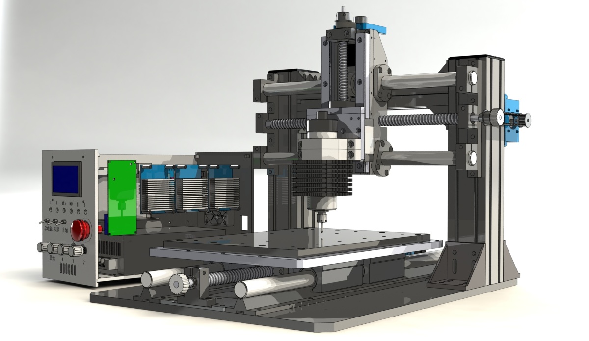
Modeling in Solidworks
There are lots of improvement here.The first one is the working dimension.After using previous machine for a few month I realized that it’s kind of small.Sometimes,lot of materials come with a size of 20×30 cm,and I had to cut it to fit in on the platform.So lots of materials were wasted because the rest of the material is too small to fix tight or make anything.That’s why I decided to make the X and Y size to 22×32 cm.Also,I increse the Z axis so that I can change the tool bits easily or maybe I can use a clamp on the platform.


Base
The base is made of 10mm aluminum plate.All I need to do is to locate some holes and drill them.The bridge between the two pillars are rock solid and can be used as a handle when I move the machine.

Y Axis
This time I canceled the aluminum profile on the platform to make it more compact.To compensate the trouble of fixing the item I drilled evenly distributed holes on the edge to mount the clamps.On the platform there’s actually a PVC plate to protect the aluminum plate.


X Axis
Actually the rod holder in the picture below is not the one on the real machine.It’s just an attempt to simplify the three separated holder design.Turned out it’s not a good ideal because I could buy those standard holders for a few bucks but I need to spend lots of time to make such a equivilent part.And this design actually didn’t bring any good.Perhaps it’s good for mass production design(As I recalled now,the reason why I wanted to make a 3-in-1 holder is to reduce the assembly error and keep the rods and screw parallel.Because I didn’t have professional calibration tool at the time and I wanted to make assembly easy.But after weighing the trade-off of the cost and tolerance I decided to go for the cheap one,sad fact of life :P).


Z Axis
Just like X axis,I used a timing belt to reduce the height.And I used rails instead of rods to reduce the size and increase the strength.Rails are three or four times more expensive than rods and hence only used on Z axis.Also the ball screw drive has a smaller diameter comparing to the X and Y axis.

Spindle
This tiny spindle is a beast!I searched all the spindles on the market and no one can beat this.It has a small diameter but has 300W power output.It can run 27,000 rpm and has a ceremic bearing to prevent the heat.The only con is that this one is fan cooling but not water cooling.So it’s a little bit noisy.I made a heat sink from a aluminum plate to help recuding the heat.


X,Z,and Spindle

X,Y,Z,and Spindle

Machine Photos


A closeup of the Controller,kind of messy.You may see there are lots of slots unused because I used this control box to test both my own control software and a commercial one.


More photos.


Machine at work.So messy…:P

Sampling Photos
Here are some of the parts made by this machine.
Dragon Block


The Library of My University.


Eraser Art


PVC Skull.Newbie machining..


PCB Etching


Aluminum Parts


Miscellaneous Parts


More Reading
This project is a part of the whole CNC project.
Check this post if you’re interested in controller developing.
Check here if you’re interested in CAM software developing,which generates machining toolpath for PCBs.
Check here to download the Solidworks model file.

Excellent, liked the compact size and design, good job))
Eagerly waiting for the continuation)
LikeLike
Glad you like it!
It’s updated.
LikeLike
Nice job, very compact and it looks very sturdy.
If you ever think of selling it as a kit, you have a potential buyer!
LikeLike
Thanks!just a hobby,not intended to commercialize,at least not now :)
LikeLike
Brilliant design! Thanks for sharing the idea of 3-in-1 X Axis rod holder! Would use it on my next upgrade.
LikeLike
Thanks Alex.I didn’t mention the downside of such design.If you make the 3 holders in one piece then you don’t have any chance to adjust the parallel and you need to make sure to reserve enough tolerance so that these rods can align well with the holes.That said,you need a machine with high precision to make these holders.
LikeLike
Malcolm,
What are the dimensions of aluminium pillars? What types of bolts and nuts did you use? Are there any backlash after some period of using?
LikeLike
Those pillars are 60×60 mm,and the bridge between them is 30×60 mm.These are GB(Chinese) standard so they work well with normal M5 boilts and square M5 nuts. There’s another standard called Europe Standard as far as I know,which has a trapezoidal cut away view so it can only works with special boat shape nuts. I’ve been using it for more than a year but I didn’t notice any sensible backlash.
LikeLike
Hey Malcolm,
Nice, well-thought out design (came here from GrabCAD).
What did you use for the bearings on the smooth rods? Are these the inexpensive but popular China-made SBR16UU type bearings? If so, what do you think of them? I’ve heard mixed reviews.
The speed of PCB engraving on the youtube video was incredible, and convinced me I should try to build one of these!
Cheers,
Anders
LikeLike
Hi Anders,
Yes,they are China made SBR series bearing.Quite decent and slightly loose fit.They come with a screw to tune the tightness,which is really handy.Good luck.
Malcolm
LikeLike
Hey Malcolm,
Just got the bearings shipped in, pretty good (a bit noisy, but I detect almost zero slop!), thanks for the suggestion! I’m setting things up in a similar fashion to your design, with some custom adjustments such as GT2 timing belt instead of leadscrew.
That said, I wanted to ask what torque motors you used… Do you think 10 kg-cm (= 140 oz-in) steppers that I have are powerful enough for the weights associated with your build? My goal is to mill aluminum, but speed is not important for me.
LikeLike
Good to hear that! The stepper motor I used claimed to have 7kg/cm torque output and it can mill the 60 series aluminum at 500 mm/min and 0.5mm depth. You said that speed is not important but you should be aware that the belt increases the speed and decreases the torque comparing to the lead screw. So if you use timing belt,then you need to increase the motor torque a little bit.The pith of the lead screw is 5mm,you need to calculate how much distance the belt travel and then calculate the ratio of these two settings.Then you’ll know roughly how much torque you want.Also the power of the spindle plays an important role.
LikeLike
Hi Malcolm,
Thank you for sharing this amazing machine with us.
I’m thinking of building a CNC machine for myself for a long time now, and I’m currently gathering usefull information.
I was wondering if you would like to share with me what the rough costs were to build this machine.
And do you have a sort of list with used materials/components?
Thanks in advance,
Keep up the good work!
Marcel
LikeLike