This post will introduce the second CNC machine I built.Why does a electronics student build a CNC machine anyway?Part of the reason is I love mechanics,but the main reason is that I want a machine that helps me to make PCB for my personal projects,as well as to make some simple parts.At the time I didn’t have that much money to buy a machine and also most of the inexpensive machines out there are not precise enough to make PCB.After reading some hobbyists’ post about making a CNC machine I finally got the idea how to build it.And then started my journey to the CNC world.
The first machine I made was quite immature because I’ve never build a machine before.So that one is my first experiment and I really gained a lot of experience of how to build one.So in the next build I made lots of improvement.The machine is way more robust and of high quality.And I’m quite satisfied with PCBs and parts it could make.
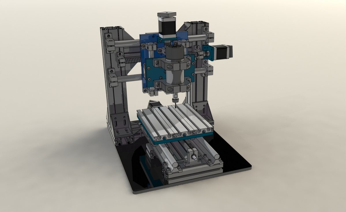
So here’s the model I built in Solidworks.Since I don’t have too much budget and tools so my goal is to make this machine as easy as possible to build.Thus,I used a lot of standard components.Also I didn’t used the moving-all-axis design instead I separated the Y axis,which actuates the platform not the X and Z axis.The merit of such design is that the machine will be more stable and easier to achieve a high accuracy.

Here’s the view of the base.Two aluminum profile pillars are used to support the heavy X and Z axis.Since the aluminum profiles can be cut by the vendors with professional tools so it saved me lots of time.Besides,these aluminum profiles are fairly cheap since these are widely used standard parts.

As I said earlier,I separated the Y axis.The Y axis mounts on the base.Another pro about these aluminum profile is that their slots work with M5 bolts and nuts well so I can easily put clamps to fix the material later on.

Here’s the X axis design.Since I only have a few budget so I didn’t use the rails.These 20 mm diameter rods are sufficient to support the X and Z axis.

And here is the Z axis.It rests on X axis,which is shown in the picture above.The weight Z axis needs to support is less than the X axis so 16mm rods are sufficient.

And then we can mount the spindle on the Z axis.The spindle holder in the picture is actually made of epoxy resin plate since I want to reduce the weight and cost.Later on it’s proven to be a bad choice.After testing for a while I finally upgraded it to an aluminum holder.There should be a lot of spindles that come with a holder on the market.I’ll suggest just go for the aluminum one.

After verifying the model in Solidworks I finally started to build it.Unfortunately I only took a few photos at that time.
This is my old machine upgrading itself. :)


And here are some of the parts built.


After putting these together and a long time of calibrating I finally finish the build.


Let’s make some stuff with this machine!Since I’m an electronics student,of course I’m going to make some PCBs to test it.It seems pretty well.


And it can cut Acrylic,PVC,and aluminum too.


And finally upgrading itself to make it more handy.To make it more easy to observe the object and locate the origin I made a LED ring and laser cross.


Update
I’ve uploaded the Solidwroks model on my GrabCAD.

Amazing!
LikeLike
Thanks! :)
LikeLike
It’s very cool project! Can you give lot info about price of all materials for this CNC?
LikeLike
Hi AHTOH,
I’ll post the BOM in a few days when I have time.But the price may vary due to where you buy these materials from.You can export the BOM in solidworks and check the price if you’re hurry now.
Malcolm
LikeLike
Great! Can you be so kind to make separate article about this LED ring with laser cross? It seems to be very handy add-on for cnc-machine. Thanks!
LikeLike