This post is to introduce the self-balancing smart car I built in 2013.My teammate and I spent several months to build a self-balancing car from a RC car chassis,and we also made most of the hardware modules and coded overnight just want to make it run faster and faster before the contest.Still remember the day when we competed with hundreds of teams from other universities :)
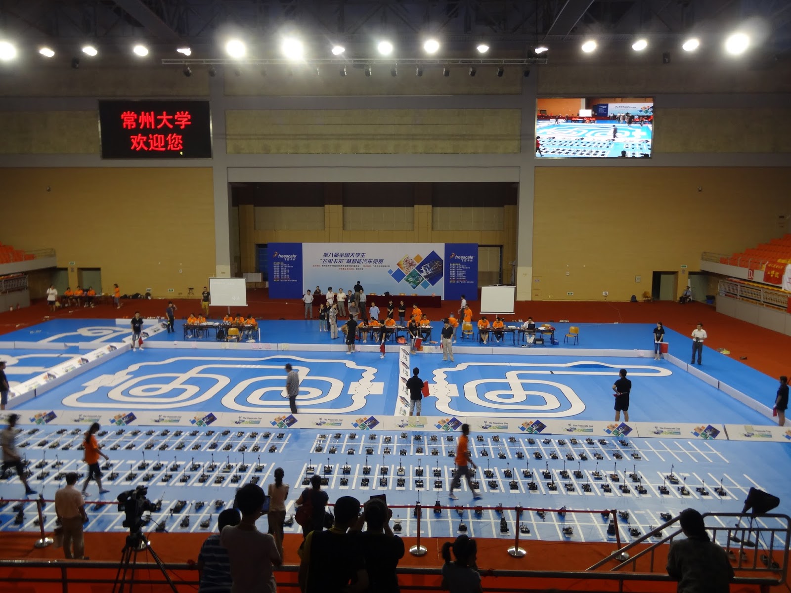
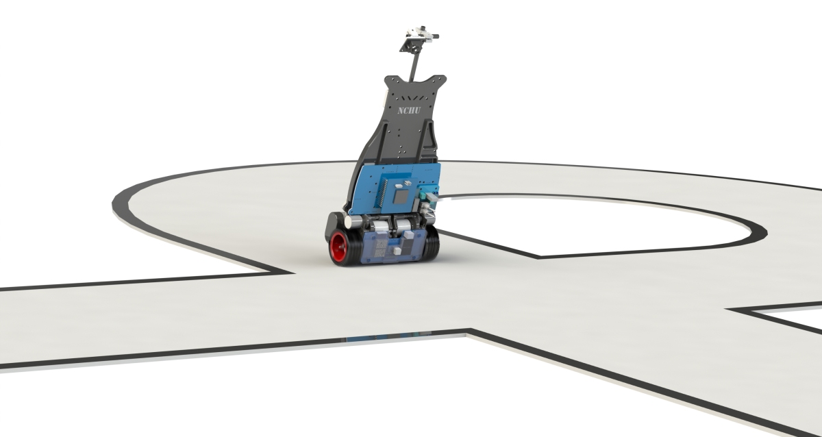
In the pictures below,you can see the car chassis we got at the beginning and the one we built for the contest. Lots of modules were made and lots of sensors were used in order to make it run and autopilot along the race track.


Control Theory
The diagram below shows how the system keep the car balanced.

So there are mainly three tasks need to be solved:
1.Keeping the car balanced.Using a PID to control the two motors to keep balanced.
2.Controlling the speed.Using a closed loop speed PID controller to achieve speed control.
3.Autopilot control.Using a PID to generate difference speeds for two motors to steer.
Among the three tasks,the first one is the most important one.The output of all the PID controllers will add up to the motors,so speed control and autopilot control are actually a sort of interference to the balancing controller.So the output of these two controllers should be smooth and limited,and keep the interference minimal.
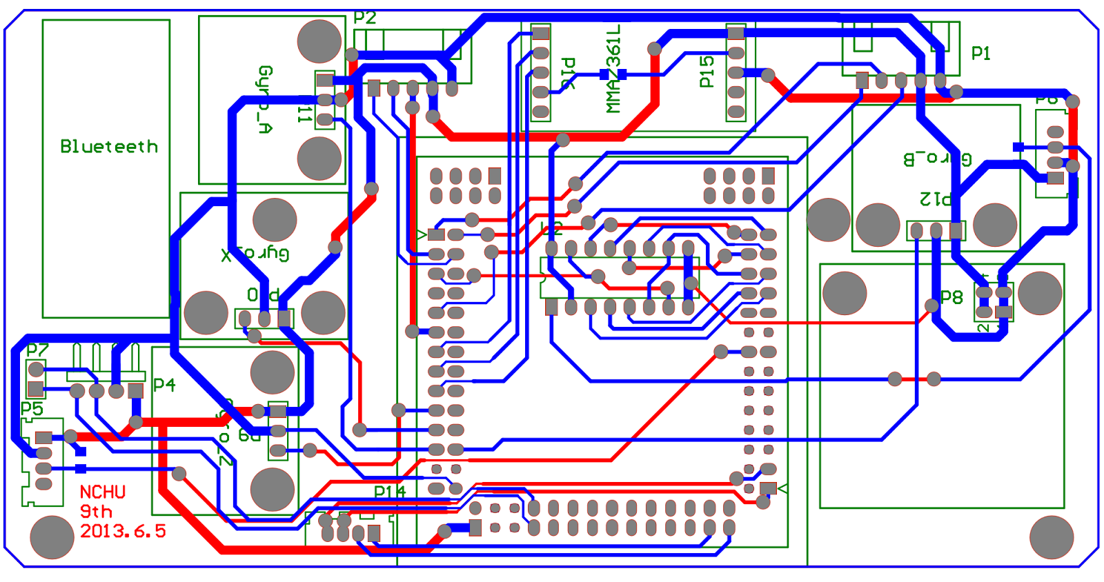
Hardware Design
To implement the control algorithm above,there are several sensors/signals needed:
- Gyroscopes.For detecting the yaw and pitch angle.
- Accelerometer.For detecting angles,work with gyroscopes.
- Encoders.For measuring wheels speed.
- Linear CCD. For detecting road information.
Also,we need these modules to make the car run.
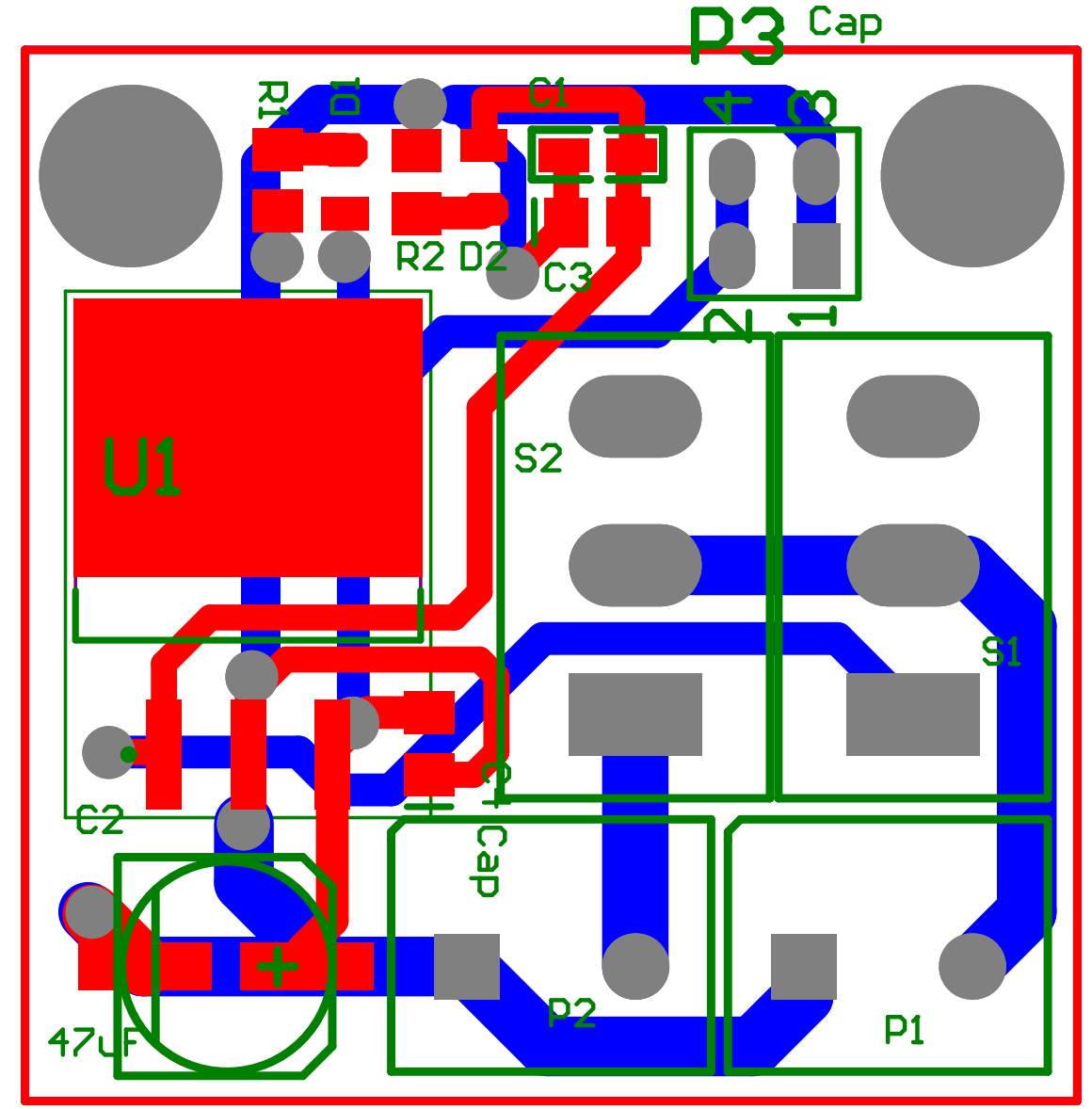
- Power module.For regulating the battery and supply different voltage level for the system
- Motor Driver.Since the system runs on battery the driver must be efficient,thus MOSFET H-bridge drivers are used.
- Bluetooth.For monitoring the car and debugging while running.
- User interface.Several switches are used to configure the parameters offline.


Microcontroller
Since this contest is sponsored by Freescale,so the microcontroller is designated.The one we used is MC9S12XS128,a 16-bit microcontroller.
Power module
Linear CCD module
Gyro/Accel module

H bridge drive

Software Design
The workflow of the software includes mainly three stages,hardware initialization,calibration,and super loop,which runs the main control tasks.In the hardware initialization stage,we need to initialize the PLL,MCU ports,PWM modules,encoder module,UART module,ADC module,and timer module.After that we need to calibrate the CCD module,gyro and accelerometer module.In calibration stage,we need to keep the car still and face the CCD to the race track.
Here is the code for calibrating the linear CCD module.The main purpose of this snippet is to calculate the threshold of the pixels so that we can use this value to recognize the race track later on.
void CCDCalibration()
{
  int i;
  //There are actually two cameras on the car for experiment,
  //in this code,only one is used.
  RD_CCD(0);
  for(i=0;i<10;i++)
  {
      //Delay some time between two sampling
      Dly_ms(ccdMultiple*5-1);
      RD_CCD(0);
      CalculateCCD0();
      Threshold+=CCDAvr0;
  }
  //Calculate the average value
  Threshold/=10;
  obstacleSign=false;
}
And then we can calibrate the gyro and accelerometer.Although we can use complementary filter to filter out the gyro drift,the result will be better if we can first measure the drift and minimize it.The gravity magnitude value can be used to determine the complementary coefficient dynamically.Since the accelerometer measure the acceleration force applied on the car,so the value is the sum of gravity,vibration,and motion.If the value is way larger than gravity,that means the value of accelerometer is not suitable for calculating the car angle and we should trust our gyro more and thus reduce the accelerometer coefficient.
int samplecounter=0,sampletime=10, sampleSign=1;
float  tempGyroOffsetZ1=0,tempGyroOffsetX1=0,tempGyroOffsetX2=0;
float tempAccX=0,tempAccY=0,tempAccZ=0;

void AccGyroCalibration() {

  for(;samplecounter<sampletime;samplecounter++)
  {
    getAD();
    tempGyroOffsetZ1+=testGyroZ1;
    tempGyroOffsetX1+=testGyroX1;
    tempAccX+=angleAX;
    tempAccY+=angleAY;
    tempAccZ+=angleAZ;
    //Dly_ms(1);
  }

  gyroOffset=tempGyroOffsetZ1/sampletime;
  TLYLDZ1=tempGyroOffsetZ1/sampletime;
  TLYLDX1=tempGyroOffsetX1/sampletime;

  tempAccX=(tempAccX*5/4096*1000/AccSense)/sampletime;
  tempAccY=(tempAccY*5/4096*1000/AccSense)/sampletime;
  tempAccZ=(tempAccZ*5/4096*1000/AccSense)/sampletime;

  //Calculate the gravity magnitude when the car is still
  gravityG=sqrt(tempAccX*tempAccX
                 +tempAccY*tempAccY+tempAccZ*tempAccZ);

  uart0_putstr("\ngravityG=");
  uart0_putf(gravityG);
  uart0_putchar('\n');
  getAD ();
  angleFilter2=-atan2(angleAX,angleAZ)*180/PI;
  uart0_putstr("\n Acc Gyro Init Done\n");
}
After calibration,we can start the control tasks.From this stage on I used background and foreground framework for programming.Background is super loop which runs some normal task which don’t have very high priorities and will be preempted by foreground tasks.Foreground is an ISR(Interrupt Service Routine) triggered by a timer every 5 ms,in which runs all the critical control tasks.Not all the tasks will run in every cycle,e.g.,speed control is called every 10 cycles,which is 50ms,because the car can’t react to any shorter speed control period.
Background tasks includes:
1.CCD data transmitting through Bluetooth
2.Debug information logging
3.Start/stop car
4.Run time profiling
Foreground tasks includes:
1.Set up the parameters using switches
2.Read gyro and acc and calculate angles
3.Read CCD and do image detection,starting line detection
4.Do speed control
5.Do direction control
6.Combine result and drive the motor
Difficulties
1.Acc/gyro fusion
2.Car body control(balancing,navigation,speed)
3.Perception issues(CCD distortion,exposure control,image edge detection,trajectory calculation)
1.Acc/gyro fusion
void AngleCalculate (void)
{
    unsigned long time=0;

    time1=micros();

    tempX=angleAX*5/4096*1000/AccSense;
    tempY=angleAY*5/4096*1000/AccSense;
    tempZ=angleAZ*5/4096*1000/AccSense;

    angleA=-atan2(angleAX,angleAZ)*180/PI;
    gravity=sqrt(tempX*tempX+tempY*tempY+tempZ*tempZ);
     //angleA2=angleAZ/AccSense;
    angleA=FIR(angleA);
    if(debug)
    {
	gravityError=fabs(gravity-gravityG);
	if(gravityError>gravityVibrationGate)//avoid vibration
	{
	  weightFlag=10;
	  weight=1;
	}
	else
	{
	  weight=weight2+(weight1-weight2)
                 *gravityError/gravityVibrationGate;
	  weightFlag=(weight-weight2)*100;
	 }
    }

    time=micros()-gyroTimer;
    gyroTimeTest=time;
    gyroTimer=micros();
    if(time>50000)  //50ms,timeout
     angleG2=0;     //large delay effects the gyro integration
    else
     angleG2=(testGyroZ1-TLYLDZ1)*5/4096*1.5/5.1/GyroSense2*time/1000;

    angleFilter2=angleA*(1-weight)+(angleG2+angleFilter2)*weight;

    timer1=micros()-time1;
}
2.Car body control
The body control consists of three PID controllers.Here’s the code of the balancing control.
void PID()
 {
	 int k=1;
	 Error=Setpoint-Input;
	 Error=FIR3(Error);

	 ValueK=k;
	 dErr=testGyroZ1-TLYLDZ1;   //kp=1900,kd=20;
	  {
		Output=kp*Error*k-kd*dErr*k;
		val_kp=kp*Error;
		val_kd=kd*dErr;
	  }

//If the car error is larger than 45,we should shut down the car,
//otherwise the car will loose control and cause damage
	if(fabs(Error)>45)
		Output=0;
	LastErr=Error;
}
3.Perception issues
Before I talk about the algorithm I used on my car let’s take a look at the race track my car ran on.Here’s the race track a few years ago before the contest I joined.At that time the tracks were simpler,there were long straight track,big curve,cross road,zigzag road,and slope.But it’s still very challenging if you wanna achieve a high speed.

The race track is changing every year and it becomes fairly complicated in 2013.Here’s what the race track looked like in the contest I joined.Besides all the elements in the previous years,there were some dash zigzag road and bump road.But there’s no black line in the middle anymore,instead it became two lines at the edge of tracks,which means it is more complicated to recognize the track.

There are many ways to detect the road.But to ensure the fairness of the game we were asked to use only linear CCD sensor.Here is what the race track look like from a linear CCD’s view.Basically it’s a string of pixels that range from 0 to 255,indicating the color changing from black to white.

So what’s the difficulty about recognizing the race track?
1.Dependency of speed ,pitch angle,and vision
The faster the car goes,the lower the pitch angle would be,and the shorter the vision would be.That means the vision length is changing during the contest,which must be taken into consideration when writing algorithm.Suppose you just got out of the crazy zigzag road and entered a very long straight track,on which you wanna run as fast as possible to minimize the time.However,there’s a sharp U turn at the end of the road and your car didn’t see it because running at a high speed made it shortsighted,and when it realizes a corner is coming it’s already to late to brake,and boom ,the car went out of the track and flipped over.

2.Trade-off of vision width and length
The CCD sensor has 128 dot of pixels.That means,if you tune the sensor up and let it see further,the race track it perceives will become shorter,which make the resolution lower.But you see further and you gain more time to react.

3.Interference of vibration,ambient light,sharp turn,and dash road
The dash zigzag road is a huge challenge,lots of team ran of out this crazy zigzag road and failed.One way to solve this problem is to use a FIR low pass filter to smooth out the calculated center line.

Check out my code on github.

You are amazing. Good Luck frm india.
LikeLike
Thanks,Rain!
This post is actually not complete.Trying to find some time to complete the software part..
LikeLike