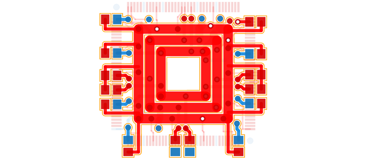
This project was done 1 year after my CNC controller project and it’s suspended in Feb 2015 because I had to put my effort into my graduate study and put this project aside.Maybe I’ll pick it up someday.The purpose of this project is to create a handy opensource PCB CAM software for CNC milling and sharpening my C++ programming skill.
Before I introduce my software,let’s take a look at the rundown process of making a PCB from layout to prototype using a CNC router.


● support most common pads(round,rectangle,oval,teardrop,etc) and straight tracks.
● support up to two layers(top & bottom)
● automatically detect contour path for cutting the board shape
● generate tool-path using single tool bit
● automatically Design Rule Check and show the collided path
● tool library management
Implementation
This post will focus on these following topics.It really takes time to present each part and I’ll update this post from time to time.So stay tuned if you’re interested in writing a CAM software . :)
1.Gerber file interpretation
2.Tracks and pads processing
3.Toolpath generation
4.Miscellaneous(Tool bits management,visualization,etc)
Gerber File Interpretation
Reading gerber file is the first problem I need to solve in this software.Currently the software only takes gerber files as input because it’s a lot of works to support all the EDA softwares.Rather,I only choose to support gerber format,RS-274X to be more specific,because it’s like a standard format that most of the EDA tools support.However,I only tested the gerber files exported by Altium Designer and it has some problems with files that produced by Eagle,or other tools.
This post will be mainly explaining the codes I wrote and the ideal behind the codes.I didn’t upload the codes to my Github since I haven’t finished commenting the code.Once it’s done I’ll opensource the projects.
The gerber interpretation is developed under “Gerber RS-274X Format User’s Guide”.Reading the guide will definitely help you understand the ideal of interpreting gerber files.
Here’s a sample of Gerber code.This snippet draws a number ‘1’.
%FSTAX23Y23*%
%MOIN*%
%SFA1B1*%
%IPPOS*%
%ADD10C,0.010000*%
%LNn1-1*%
%LPD*%
G54D10*
X002Y001D02*
X00239D01*
X00219*
Y00218*
X002Y00198*
M02*

Here’s the quick explanation of the data above.
%FSTAX23Y23*%
A line start with F is usually the first line of the file.This parameter is a Format Statement (FS) describing how the coordinate data in the file should be interpreted (in this case, 4.2 format for both X and Y coordinates).
%ADD10C,0.010000*%
Aperture parameters definition.Aperture format:
%ADD<D-code number><aperture type>,<modifier>[X<modifer>]*%
where:
ADD – the AD parameter and D (for D-code)
<D-code number> – the D-code number being defined (10 – 999)
<aperture type> – the aperture descriptions.Standar types:
C – Circle
R – Rectangle or squre
O – Obround(oval)
P – Regular polygon
<modifier> – depends on aperture type,X to separate each modifier.
examples:
%ADD10C,.025*% – D-code 10: 25 mil round
%ADD22R,.050X.050X.027*% – D-code 22: 50 mil square with 27mil round hole
%ADD57O,.030X.040X.015*% – D-code 57: obround 30×40 mil with 15 mil round hole
D Codes definition:
D01(D2) – Draw line,exposure on.
D02(D2) – Exposure off.This is like G00 in GCode,which is rapid positioning.
D03(D3) – Flash aperture.Used for exposuring a pad.
After we figure out what those symbols mean we can start interpreting. The interpretation process is done in two steps:
1.Read the raw ASCII gerber data,check if there’s any error,and put data in different places.E.g.,Extract the aperture definition and put them in Hash tables.Here’s the list used for storing the raw data:

And here’s the Hash table for storing the aperture information:

2.Interpret each line and put them in more complex data structures. E.g.,extract pads and tracks information from the lines,combine the aperture information from the Hash table.So here’s the list used for storing the pads:

And the list used for storing the tracks:

After these two steps we basically extracted all the information we need from the gerber file.Then what else do we need to do?The next step is to reconstruct the PCB from these gerber data.Since the gerber file only records the trajectory of the PCB so we lose lots of information,such as net,hole size,board shape,etc.However,these information could be reconstructed from the gerber data.For example,the net could be found by collision detection because all the tracks and pads in one net must be physically connected.This is exactly what I do in the later on process.However,in this part I’ve done some works to make the collision detection algorithm more efficient.
Under writing…


2 thoughts on “GerberCAM – Opensource PCB G-code Generator”